External Setup:
Plug in the switcher power cord and connect it to the switcher.
Plug an SDI cord from each camera into the SDI inputs on the back of the switcher.
Plug your laptop into the HDMI input 5 or 6.
Format a SD using one of your other devices. Insert it into the right side of the switcher. IMPORTANT: The SD Card Slot is labeled on the right side of the switcher. It is the bottom slot. Do no put the card anywhere but that bottom slot, other slots are for the internal fan.
Internal Setup:
Power on the switcher, button is on top row towards the right, and labeled “power”
On the bottom left of the controls, the “SRC 1” button controls which audio is on channel one, “SRC 2” controls which audio is on channel 2, etc.
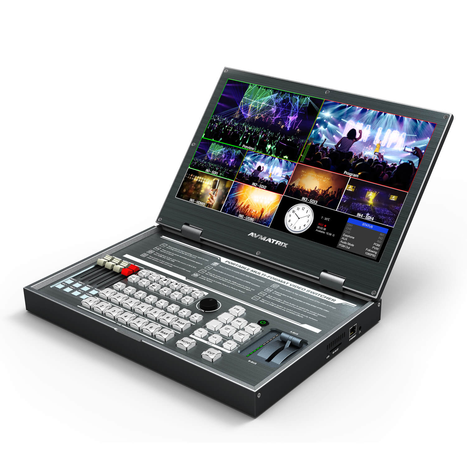
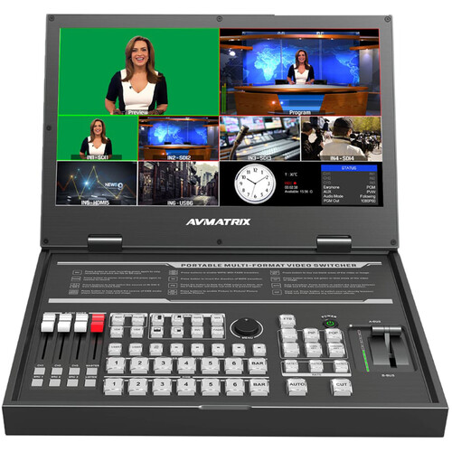
On the bottom right of the screen, the “Status” box shows which input is going to which audio channel.
On the bottom half of the screen, you can view the connected cameras and computers. Check which input they are by looking at the label of the box you view them on. The first 3 characters of the label should be “IN1”, “IN2” etc.
Match the cameras and computers inputs to the audio channels by pressing the “SRC 1” SRC 2” & “SRC 3” buttons. Example: If your cameras are showing the the box labeled “IN3” and IN4” and your computer is showing in the box labeled “IN5”; press “SRC 1” until the status box on the bottom right of the screen shows “CH1” as “IN3”. Then press “SRC 2” until the status box shows “CH2” as “IN4”, then press “SRC 3” until the status box shows “CH3” as “IN5”.
Press the “Master” button on the bottom left of the control panel. It should now be lit.
Control which audio is being used for the switcher’s recording by using the “CH1” CH2” and “CH3” buttons on the bottom left of the switcher. Whichever “CH” your main audio is tied to needs to be lit, which you do by pressing the appropriate “CH” button once. When it is lit, it is going to the program. Example: If the camera your lapel mics are connected to is “IN3” and in the previous step you connected “IN3” to “CH1”; you should press the “CH1” button.
If you want audio being recorded on the switcher from more than one device, press the appropriate “CH” button for the other cameras/laptops as well.
Press the “Listen” button on the bottom left of the control panel until the “Status” box on the bottom right of the screen shows “Earphone” as “PGM”. Your headphones should now have the audio you want being recorded on the switcher.
Note: You can press the “Listen” button to check audio levels on your other cameras as well, however you should mostly be listening to “PGM” to make sure your main audio is correct.
Operating Switcher:
On the bottom half of the screen, you can view the connected cameras and computers. Check which input they are by looking at the label of the box you view them on. The first 3 characters of the label should be “IN1”, “IN2” etc. The number after “IN” represents which input the devices you’ve connected are.
There are two bars labeled “1” “2” “3” “4” “5” “6” “Color Bar” on the bottom center of the control panel. The upper of these two bars controls which input is being sent to the program recorded by the switcher. The numbers represent the devices (cameras/laptops) you have connected to the switcher. When you press a button, it should turn red, and the associated input device should show in the top right of the screen. Control which input you cut to by using these buttons.
When you are about to begin, press the “REC” button on the top row, left half of the control panel. Stop recording when done by pressing the “REC” button again.
Lower Thirds:
You only need to follow these steps if you are intending to utilize the AVMATRIX to insert already created lower thirds into you program.
Before recording, press the “Chroma Key” button”
The box on the bottom right of the screen should now be labeled “Key”
Turn the circular knob labeled “Menu” until “Background” is highlighted in the box on the screen
Press the circular “Menu” knob
“Blue” should now be highlighted in the box on the screen.
Turn the circular “Menu” knob
The box on the screen should now have “Background” as “Green”
Press the “Chroma Key” button again.
There are two bars labeled “1” “2” “3” “4” “5” “6” “Color Bar” on the bottom center of the control panel. The upper of these two bars controls which input is being sent to the program recorded by the switcher. The lower of these two bars controls which input is being sent to the preview window. The numbers represent the devices (cameras/laptops) you have connected to the switcher.
When recording and ready to insert your lower third, open your lower third file on your laptop.
Press the appropriate number button to send the input you want to put the lower third over to the “Program” window on the top right of the screen.
Press the appropriate number button to send your laptop lower third input to the “Preview” screen on the top left of the switcher.
Press the “Chroma Key” button.
To display your lower third in the program, move the lever on the right side of the control panel to opposite of wherever it is currently.
When done displaying the lower third, move the lever on the right side of the control panel back to it’s original position.
Press the “Chroma “Key” button again. DO NOT FORGET THIS STEP
You can now continue as usual with switching.
11 thoughts on “AVMATRIX Conference Settings”
mail order prescription drugs from canada
legitimate online canadian pharmacies
online prescription drugs
canadian rx pharmacy online
no prior prescription required pharmacy
prescription drugs canada
pharmacy canada
international pharmacies that ship to the usa
Slottica Casino to propozycja dla graczy szukających nowoczesnej platformy do gry online i wygodnego dostępu do szerokiej oferty rozrywki. Serwis wyróżnia się intuicyjnym interfejsem, sprawną obsługą płatności oraz atrakcyjnym wyborem gier dopasowanych do różnych preferencji. Na szczególną uwagę zasługują wysokie standardy bezpieczeństwa, w tym szyfrowanie danych i rozwiązania chroniące prywatność użytkowników na każdym etapie korzystania z platformy. Dzięki temu gracze mogą skupić się na zabawie, mając pewność, że ich dane osobowe i finansowe są odpowiednio zabezpieczone. To jeden z ciekawszych wyborów dla osób zastanawiających się, gdzie grać online w bezpieczny i komfortowy sposób.
Vavada to znane kasyno online, które działa również w Polsce. Strona przyciąga graczy szeroką ofertą gier, przejrzystymi warunkami i obsługą w PLN (zł). Bonus powitalny oraz intuicyjna obsługa sprawiają, że platforma zdobyła popularność wśród polskich użytkowników.
Vavada to znane kasyno online, które działa również w Polsce. Strona przyciąga graczy szeroką ofertą gier, przejrzystymi warunkami i obsługą w PLN (zł). Bonus powitalny oraz intuicyjna obsługa sprawiają, że platforma zdobyła popularność wśród polskich użytkowników.